Procedural Planet Generation
I’ve experimented before with procgen with standard rectangular heightmaps, but was interested in applying the concept to a sphere, like a planet. The advantages of using a spherical representation are:
- Eliminating distortions due to rectangular projections (e.g. Mercator)
- Sure, at the end of the day it’s viewed on a rectangular screen, but think of the view as Google Earth rather than Google Maps.
- This also makes game logic like pathfinding for shipping lanes and flights more realistic, as great circles are chosen that may go through the Arctic.
- Transition seamlessly from a 3D outer space view to a planet surface view
Additionally, depending on the tessellation of the sphere mesh, the level of detail can be more uniform. Currently, with a rectangular grid that is mapped back to a sphere – say, along the latitude and longitude – the longitdunal lines are closer at the poles and furthest apart at the equator. If the lat/long intersections are where we place vertices, the poles are going to be more geometrically detailed.
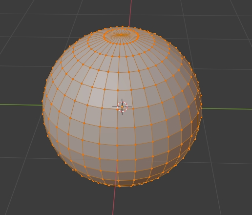
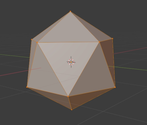
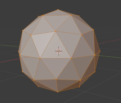
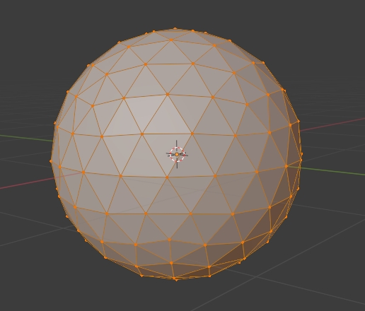
There are a few different ways of tessellating a sphere, the most popular being the UV sphere (described above) and the icosphere, which is constructed by taking an icosahedron, subdividing each face as many times as desired, and projecting the points out to the surface of the unit sphere. This construction has no polar bias and is more uniform than the UV sphere, but vertices are still a bit denser where the original corners of the icosahedron were.
Fortunately, the Fibonacci Sphere is a well known construction that optimizes for uniformity by producing vertices in a Fibonacci Spiral down the longitude of the sphere! In the below clip you can see that as I increase the number of vertices one by one, the spiral organization is kept, and the points are redistributed evenly. Notice how the poles are merely the endpoints of that spiral and are not denser than any other part of the surface.
Generating the points for a given N vertices is straightforward enough (see Stackoverflow). The real trick is then finding the triangulation of these points, i.e. which points will make up the triangle faces for the mesh, which we will need to send to the GPU to render. The solution to this problem generally is to use Delaunay’s triangulation algorithm, which produces a triangulation for a given set of points on a plane.
However, we don’t have points on a plane here, so we need to somehow transform these points on a 3D sphere onto a plane, such that when running Delaunay’s, the resulting triangulation on the plane will also be correct for the sphere. Intuitively, this means that when transforming, points that are “neighbors” of each other on the surface of the sphere should remain “neighbors” on the plane. This is so that the algorithm creates triangles from points that are close to each other. For instance, just doing an orthographic projection onto the plane z = 0 won’t work since the northern and southern hemisphere points will be on top of each other and “neighborly”, even though they should not be connected on the sphere.
One projection that does preserve the surface’s neighborliness is the stereographic projection (think the U.N. flag). Running Delaunay’s on this projection and then using that triangulation on the sphere works nearly perfectly (and is demonstrated in the above video), except that there remains a hole in the south pole.
This is because in the stereographic projection, the south pole is the entire perimeter of the plane, and not a single point! This is easily patched however, by adding a few triangle faces manually to complete the spiral. A singularity of this sort is unavoidable, as we are mapping a sphere to a plane, and some information/relationship is necessarily lost.
With the tessellation in hand, the next part is to generate heights for each vertex on the sphere. The techniques used here are the same as one would use for a rectangular heightmap: combining multiple layers of Perlin Noise, each at different frequencies and with different weights to create fractal noise. In addition, I’m adding another noise layer by taking 1 - abs(noise) to simulate large mountain chains:
In the video, you can see me move through the noise, first for the mountain chain layer, and then for the main surface layer. You might randomize these parameters to generate different planets of the same style. Finally, I adjust the scales of the main surface layer and mountain chain layer – the last of which looks like a bizarre planet composed only of ridges! You might randomize these parameters to produce planets in an entirely different style.
For the coloring, I use a threshold that fades in/out based on the steepness of the terrain (the surface normal dotted with the radial direction) and the height of the terrain (from lowest elevation to highest). In the above example, I used red and white shades to produce a planet resembling Mars. For even finer detail, I also added a rocky normal map to the planet’s surface at a higher frequency, which you can see as the small shadowy contours that don’t shift as the noise (the actual geometry) is shifted. These selections could all be randomized as well, to produce even more planet variety.
In terms of next steps, I’d like to explore adding fluids – liquids and gases, or more colloquially, atmosphere and ocean! – to increase planet diversity. Other interesting variations would be planet size (and the associated implications on gas/rock/liquid composition), rings, and flora for inhabited planets.