Hex Strategy Map: Design
<
High Level Approach
For a while now, I’ve been interested in figuring out how the gorgeous maps in Civilization 6 are put together and rendered:
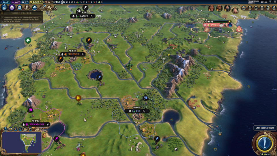
As you can see, the map is based on a hex-grid, which is most apparent when inspecting city borders, river intersections, and feature placement. However, it strikes a good balance between being readable game UI and natural looking terrain. For instance, adjacent mountains are all connected with a continuous ridge, and the rivers ebb naturally even though they roughly follow 60 degree angles.
Users create their own maps using an in-game hex-cell editor, and the maps are saved into files, for rendering at runtime. The data layout of these files might look vaguely like a CSV file:
row1: grass, grass_hill, lake, desert, sea
row2: sea, grass, desert, lake, grass, sea
...
The key point is that no artwork is included in the map files, just text-equivalent data. The game artwork components are provided by the engine and then combined at runtime to create the final product, according to the map file layout. This allows for simple authoring and easily shareable files. How does Civilization 6 take a rigid and uniform grid of hex cells and make it look so good?
Let’s consider two different approaches:
Approach 1: Tiling Hexagon Meshes
One, that the rendering is based on each hex, that is, for each hex, we create a mesh, and then glue all of them together to form the entire map, sort of like what an old-school RPG might do (but in 2D and with squares):
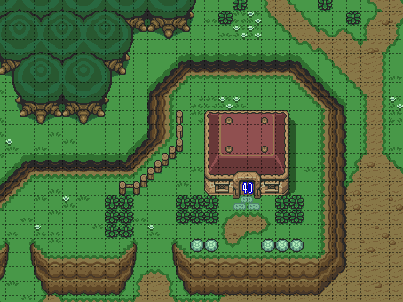
The Legend of Zelda: A Link to the Past. SNES, Nintendo, 1991.
This sounds plausible – we can save on vertex count by joining the vertices where hexes meet, and it fits the data format of the map well. For particularly flat or uniform stretches (like the seafloor), we can reduce the vertex count by removing redundant hexes by simplifying the mesh. This approach is essentially what Jasper Flick walks through in his excellent Unity Hex Map Catlike Coding Tutorials, with a lot more features, including cell elevation.
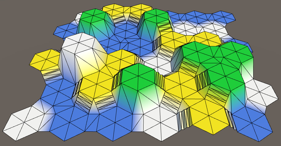
However, “handcrafting” each hex means the mesh topology is rather inflexible. To create smooth and more irregular coastlines for instance, we could add noise to each vertex position, but then we’d need to subdivide the mesh so it doesn’t look jagged. Since each hex at minimum has 24 triangles (6 for the face, 2 each for the 6 “bridge"s, 1 each for the 6 triple corners), this explodes very quickly, with very coarse granularity.
On top of that, each mesh feature, like riverbeds and cliffs, need to be “handcrafted”, that is, designed in code, which is not ideal for fast and maintainable art iteration and prevents the use of traditional 3D modelling software or 2D texturing software.
Finally, breaking the map up into chunks (for culling, to avoid rendering offscreen portions) is challenging because seam joining is more complicated when the seams are jagged hex boundaries (see the edges above), as opposed to more common rectangular seams.
Approach 2: Heightmaps
Another approach is to use terrain heightmaps. These are usually authored in dedicated level editing software like World Machine or in-engine, like with Unity’s Terrain tools, where the user “draws” a heightmap with brushes and stamps, and then textures it, and adds features in a similar way:
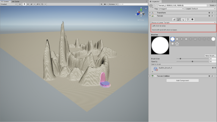
Naturally, we would not be manually creating a height, texture, and features map in-editor. These pieces of data would have to be derived at runtime from the much simpler, CSV-like map file. This technique has a few upsides over the hex-topology approach:
- Square grid topology
- Easier to partition map into chunks for culling
- More fine-grained LOD (level-of-detail) control, since our base is a 2 triangle quad. Doubling for each subdivsion yields 4, 8, 16, …
- As opposed to subdividing a hex, which is 24 triangles. Doubling for each subdivision yields 48, 96, 192 …
- More regularity means arbitrary curves can look more continuous
- Heightmap
- Terrain features can be designed with existing texturing tools like GIMP
- Can easily be serialized and inspected for debugging (and saved to disk for faster loading)
With this general approach in mind, let’s start with the map file format and work our way forward!
Tiled Editor and Map Format
Very quickly I decided I didn’t want to write my own hex map editor, plus there’s already the excellent Tiled Map Editor out there. The layers system is a good way to store per-cell data, like:
- Biome: e.g. Temperate, Desert, Coast, Sea
- Height: 0 (Underwater) or 1 (Above water)
- Terrain: Plains, Hills, Mountains
- Features: e.g. Woods, Marsh
- City Ownership: via ID#
You can see examples of this below:
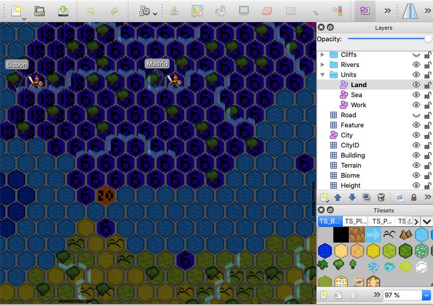
Tiled Map Editor: Southern Iberia and Morocco. Note the biome, terrain, and feature tileset on the bottom right
Cities and units are objects, with attributes like faction owner, names, and types. Note that units are split up into 3 separate movement layers, and the object IDs that Tiled assigns to each city are then used to indicate cell ownership. For instance, Madrid happens to be object #6, Lisbon is #18, and London is #20 (Gibraltar). The cells covered in 6, 18, and 20 belong to those cities, respectively.
For features that aren’t quite 1:1 with a cell, like rivers and cliffs, which are inter-cell, on edges, the following scheme is used: each cell stores information about its west, south-west, and south-east edges. This covers all possible edges (except on the edges of the map) since one cell’s east edge is simply its eastern neighbor’s west edge.
In the editor, this manifests as 3 different layers: W, SW, SE, for each kind of edge feature. It’s not just enough to have 3 different cliff palette tiles for the 3 directions on 1 layer, since it is possible to have each of the 3 edges be cliffs. You would have to have enough palette tiles to account for all (2^3 = 8) permutations. This would be even worse with rivers (3^3 = 27) since each edge also has a directionality (to indicate the river flow).
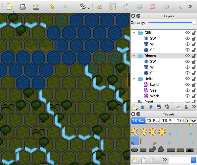
Tiled Map Editor: The Seine and the Channel. Note the cliff and river tileset on the bottom right. It’s hard to see, but the river edge tiles have an arrow indicating the water flow direction.
Nowadays, Tiled Map Editor uses JSON with CSV inside to save its files, and we can surely read this straight in. However, there is additional map data I’d like to store in the files that isn’t easily added or edited in Tiled. This includes more “map global” information, like information about each faction on the map – their name and their colors – and the game’s turn state. Turn state could perhaps be implemented in the key values of the map’s global properties, but the faction list is an array and Tiled doesn’t support that. At the same time, it would be nice to have something more quickly scannable for errors, debugging, and editing than this:
{
  "data":[10, 10, 12, 8, 9, 9, 9, 8, 12, 12, 10, 10, ...],
  "name":"Biome",
  ...
}
10,000+ entries, one for each cell, for each layer!
Plus, (probably a premature optimization) most JSON parsers load the whole file contents into memory, so 10,000+ entries for each of the ~10 layers is expensive. It would also be nice to enforce some data validation at map editing time. As a result, I wrote a Tiled script extension that invokes SQLite’s command line tool to save the data to a SQLite database file. The schema ended up resembling the Tiled file in that each layer roughly got its own table, like so:
- Factions: ID (int), Name, Color
- Cells: CellID (coords as int), Terrain, Biome, Elevation
- CellRivers: CellID, RiverSW, RiverW, RiverSE (none/up/down)
- Cities: CellID, Faction (int), Name
- CellCities: CellID, CityCellID
At runtime, this database is then queried when loading the map to build the initial world state, and then saved to to record progress.
ViewController, Model, ViewModel, View Architecture
Speaking of state, the complexity of this project made it necessary to be thoughtful of the update cycle. In particular, I wanted to avoid a naive, object-oriented implementation where the simulation/model is tightly coupled to the presentation logic. In simpler games, this is acceptable since the code complexity stays small. Other times, the world model is strongly tied to the engine’s physics simulation, which is tightly coupled to the engine’s scene graph, so this is hard to work around.
In my experience, this makes it hard to experiment, as trying a new graphical style can mean branching the entire codebase, including the simulation aspects, and vice versa. A different approach, keeping simulation and presentation separate, may be particularly well suited to the strategy genre, where there may be many frames where the game world isn’t updated at all – say, while waiting for a user action. It is also useful for multiplayer, where there may be a server running a headless instance of the program, or even for clients to easily serialize the simulation state.
In other words, avoiding something like the classic:
class Ball : MonoBehaviour {
  float mass;
  Vector3 position, velocity;
  Color borderColor, fillColor;
  Mesh mesh, particleTrail;

  void UpdatePhysics() { ... }
  void UpdateGraphics() { ... }
}
To be able to swap out different presentation modes easily, I also wanted to avoid code that explicitly tied to a single implementation or mixed the graphical updates with the simulation updates, like:
class Game {
  BallModel ballModel;
  BallView ballView;
  void Update() {
    ballModel.position += ballModel.velocity * Time.deltaTime;
    ballView.transform.position = ballModel.position;
  }
}
This is solved by putting the view behind an interface like IBallView, and thinking of the view classes as a sink output of model data. Taking a page from the traditional MVC application architecture, the pattern used throughout the project was as follows:
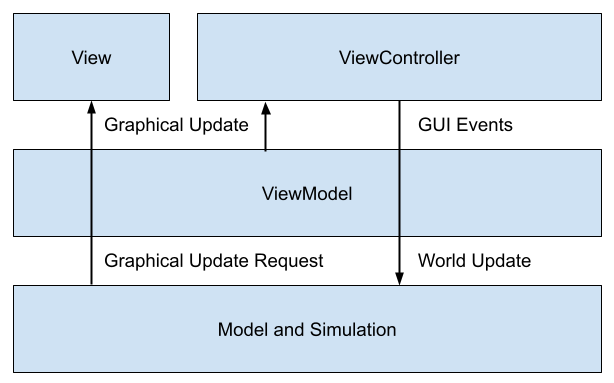
ViewController: Entrypoint. Displays GUI and receives incoming UI and input events, dispatching to theViewModel. Receives relevant model updates from theViewModelto update the UI.ViewModel: Glue code responsible for transformingViewControllerevents into Model operations and sending any relevant graphical update requests to theViewandViewController.Model: Strictly simulation data objects and algorithms to operate on them. A traditional “business data” object graph.View: Strictly graphics objects and algorithms to update heightmaps, textures, meshes, effects, and object transforms. In Unity, mostlyMonoBehavioursubclasses.
RenderRequests
Additionally, I knew beforehand that generating and updating high resolution heightmaps, textures, and meshes would be expensive, and only tolerable from scratch at initial load time. Any further changes (like if a faction takes control of a new city) would have to be as incremental and surgical as possible to minimize frame rate drops. This meant that I couldn’t push all model state onto the view objects and “resync” the entire world every frame.
Some popular UI frameworks like React solve a similar problem, where updating the actual graphics (in React’s case, the HTML DOM) is too expensive to completely resync on each update. React creates a virtual DOM tree from the current model data and diffs it with DOM tree actually displayed on screen, and then just updates the necessary parts.
This is not worth replicating exactly, since diffing every possible piece of visual data every frame would be infeasible – imagine scanning every texture on every frame to know if they have changed! Instead, the ViewModel can issue updates targeted to the View, roughly corresponding to each View “module”, with hints provided from the Model if needed. That way, not every piece of View needs to be updated each frame, and for performance sensitive parts, the ViewModel can be more specific about just what parts do need to be updated. Below is a code snippet describing the flow for updating the currently selected cell on a user click:
// Bitmask specifying what part of the view needs to be re-rendered
enum RenderComponent {
  None = 0,
  Terrain = 1,
  Units = 2,
  UI = 4,
  All = 7,
}

// Describes a request to partially re-render the view
struct RenderRequest {
  RenderComponent Updates;
  Model Model;
}

// Receives incoming UI and input events
class ViewController : MonoBehaviour {
  ViewModel viewModel;

  void Update() {
    if (Input.GetMouseButtonDown(0)) {
      viewModel.SelectUnitsOnCell(GetCellCoordsUnderCursor());
    }
  }
}

// 1. Transforms incoming UI and input events into model operations
// 2. Transforms model operation results into render requests
class ViewModel {
  Model Model;
  IView View;

  void SelectUnitsOnCell(CellCoords cellCoords) {
    // At first, assume no re-rendering is needed
    RenderComponent Updates = RenderComponent.None;

    Cell cell = Model.GetCell(cellCoords);
    if (cell.Units.Count > 0) {
      // If a cell with units is selected, the UI and units need to be re-rendered
      Model.SetSelectedUnits(cell.Units);
      Updates |= (RenderComponent.UI | RenderComponent.Units);
    }

    // Dispatch the re-render to the view
    View.Render(new RenderRequest() { Model, Updates });
  }
}
Though this design introduces significant (code) overhead, it:
- Decouples the model from the graphics
- Makes graphics and state changes more explicit
- Allows easier traceability for debugging (print the RenderRequests)
- Allows targeted changes to avoid re-rendering everything
In part 2, I’ll go over the low level rendering details which create the map at runtime.